Wireless Internet service provider Linkfor, operating in the Belgogrod region, is a client of LigoWave‘s distributor in Russia – WMD. Linkfor has over 3300 commercial clients in total and 345 of those clients are connected with LigoWave devices.
Linkfor recently set up a network with 72 CPEs connected to LigoDLB 5 -90 base-station with an integrated dual-polarized 90 degree sector antenna. The base station comes with a 18 dBi dual-polarized 90° sector antenna. All of the CPEs used for this network were LigoDLB 5 – 15s. The devices were operating in iPoll 3 mode. LigoWave’s iPoll 3 PTMP (point-to-multipoint) proprietary protocol is an innovative solution to eliminate transmission congestion and close cluster interference created in PTMP wireless installations.
The throughput was measured to be between 55 and 60 Mbps with all 72 CPEs connected. Linkfor offers the following plans for their customers: 8 Mbps, 6 Mbps and 4 Mbps. The distribution of clients with different speed plans was set as follows: 8 Mbps for 10% of clients, 6 Mbps for 20% of clients and 4Mbps for 70% of clients.
Stats
- Firmware version: APCPE.QM-1.v7.54-DEVEL.17819
- Mode: Access point (iPoll 3)
- Channel width: 20 MHz
- Number of connected CPEs: 72 (LigoDLB 5-15)
- CPE distances: 10% – 2.5-3 km/50% – 3-4 km/40% – 4-5 km
- Customer service: Internet access

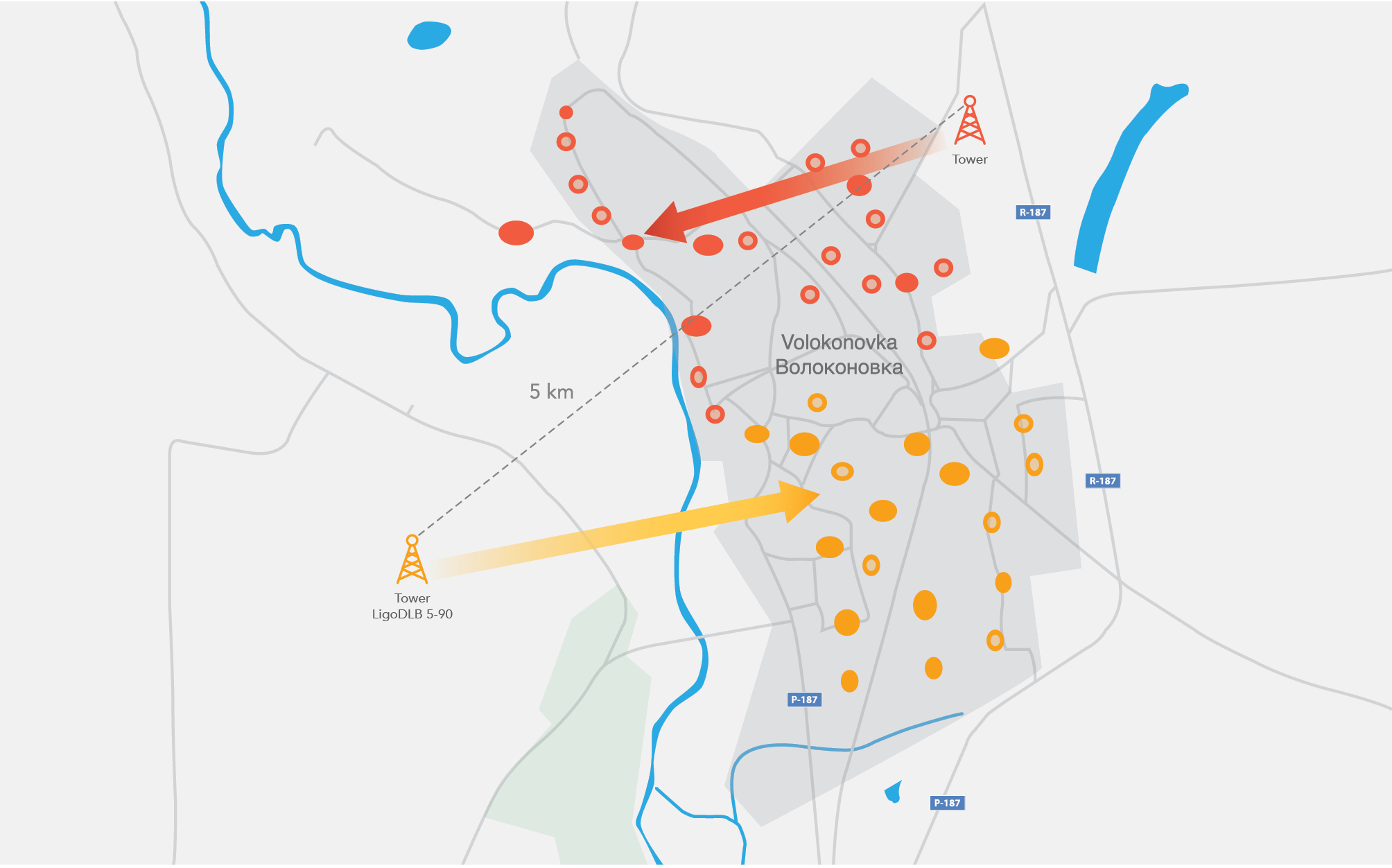
Map of the deployment area
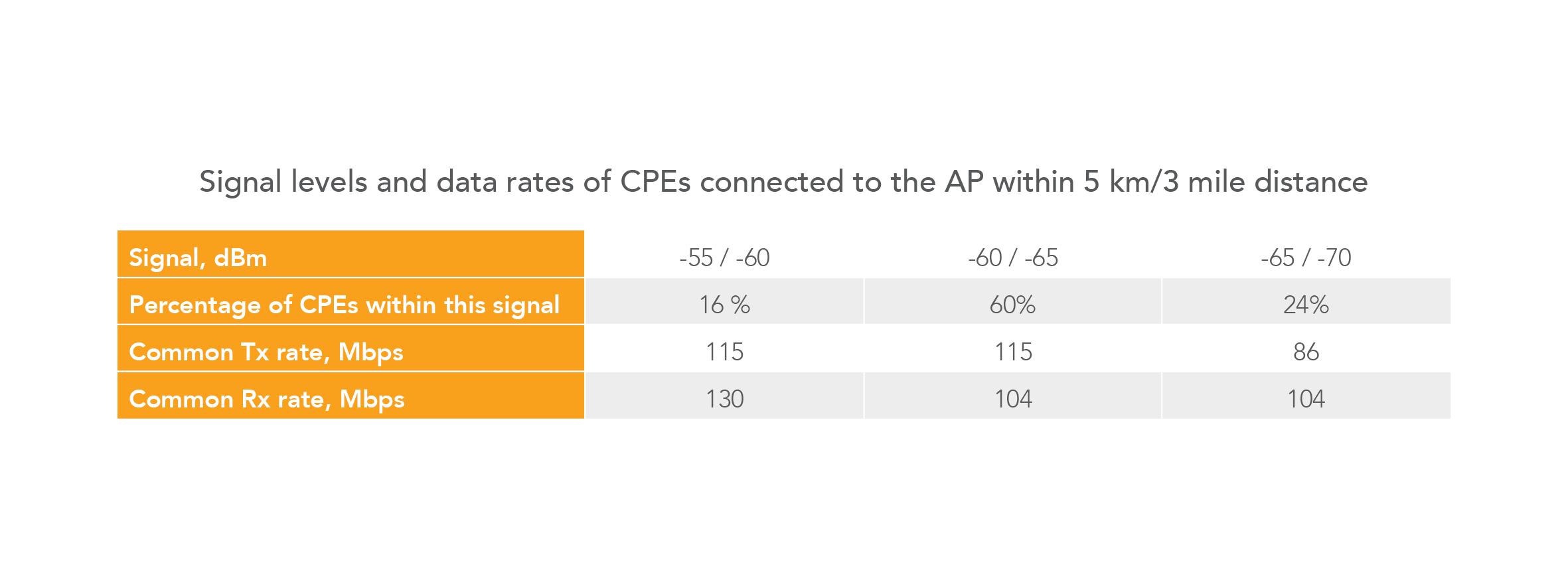
The table above shows signal levels and data rates of the client devices connected to the LigoDLB PRO 5-90-20 base-station within 5 km range. 16% of the devices fall into the category of signal levels of -55/-60, achieving common Tx/Rx rates 115/130 Mbps. More than half of the CPEs reached a signal level of -60/-65 with the common Tx/Rx rates of 115/104 Mbps. And 24% of the CPEs reached the signal level of -65/-70 dBm with the common Tx/Rx rate of 85/104 Mbps. The signal levels of even the most distant clients are within the acceptable range with the 15 dBi antenna gain.
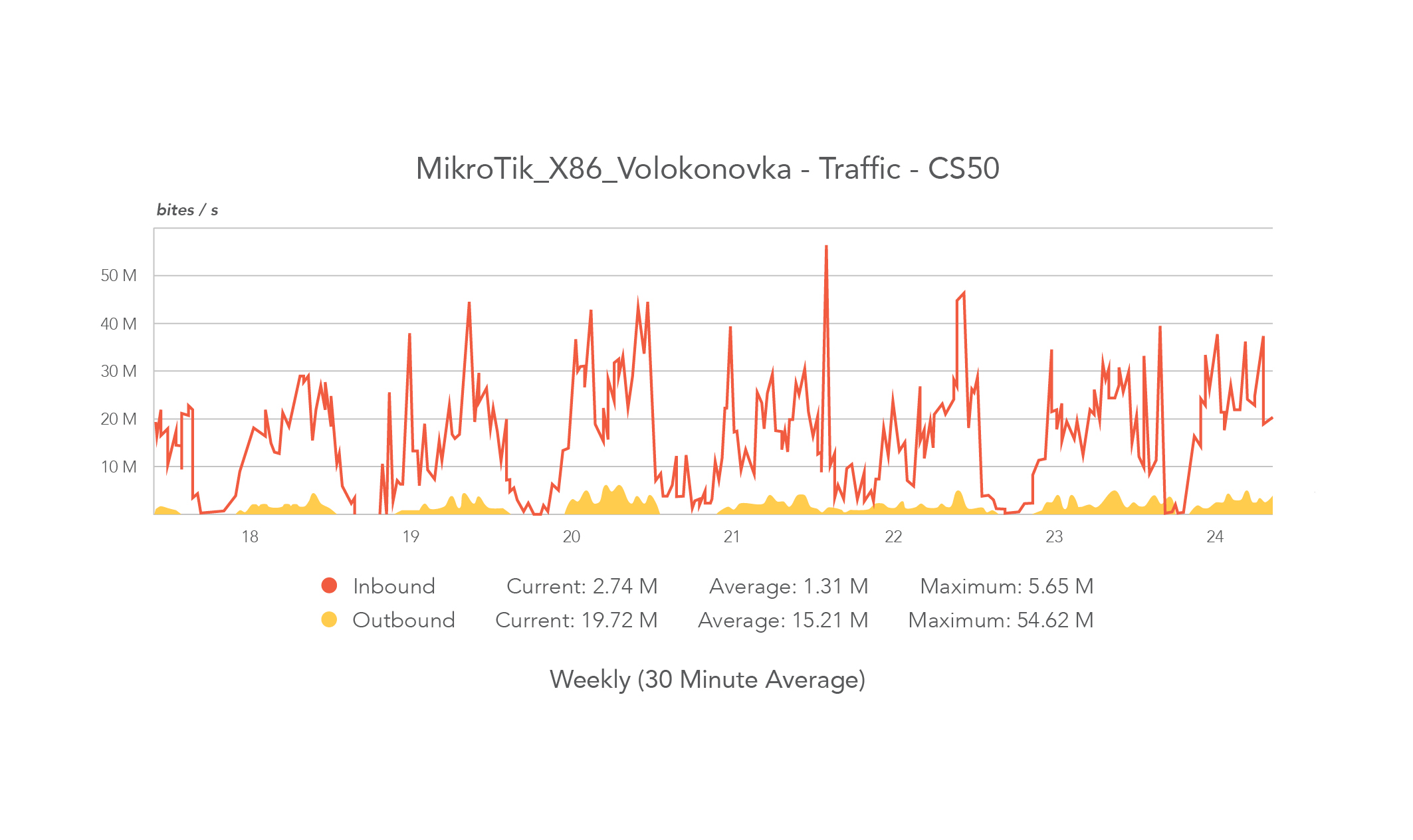 The graph above shows the throughput history of the AP with 70+ clients. The average throughput in the middle of the day is around 15 Mbps. During the evening period when client activity reaches its peak it can be seen that maximum throughput can reach up to 55 Mbps. It is important to mention, that AP is operating on a 20 MHz channel width.

The second graph is taken during the evening period when network activity is the highest. Usually in asymmetric links the downlink takes the highest portion of the wireless medium. In this case 75% of wireless medium is taken by the downlink. This is traffic coming from the AP to the CPEs. This is normal when clients are browsing or downloading various content from the Internet. The speed plans for customers are limiting both the upload and download speed. The upload is more limited compared to the download which is common practice in asymmetric link installations.

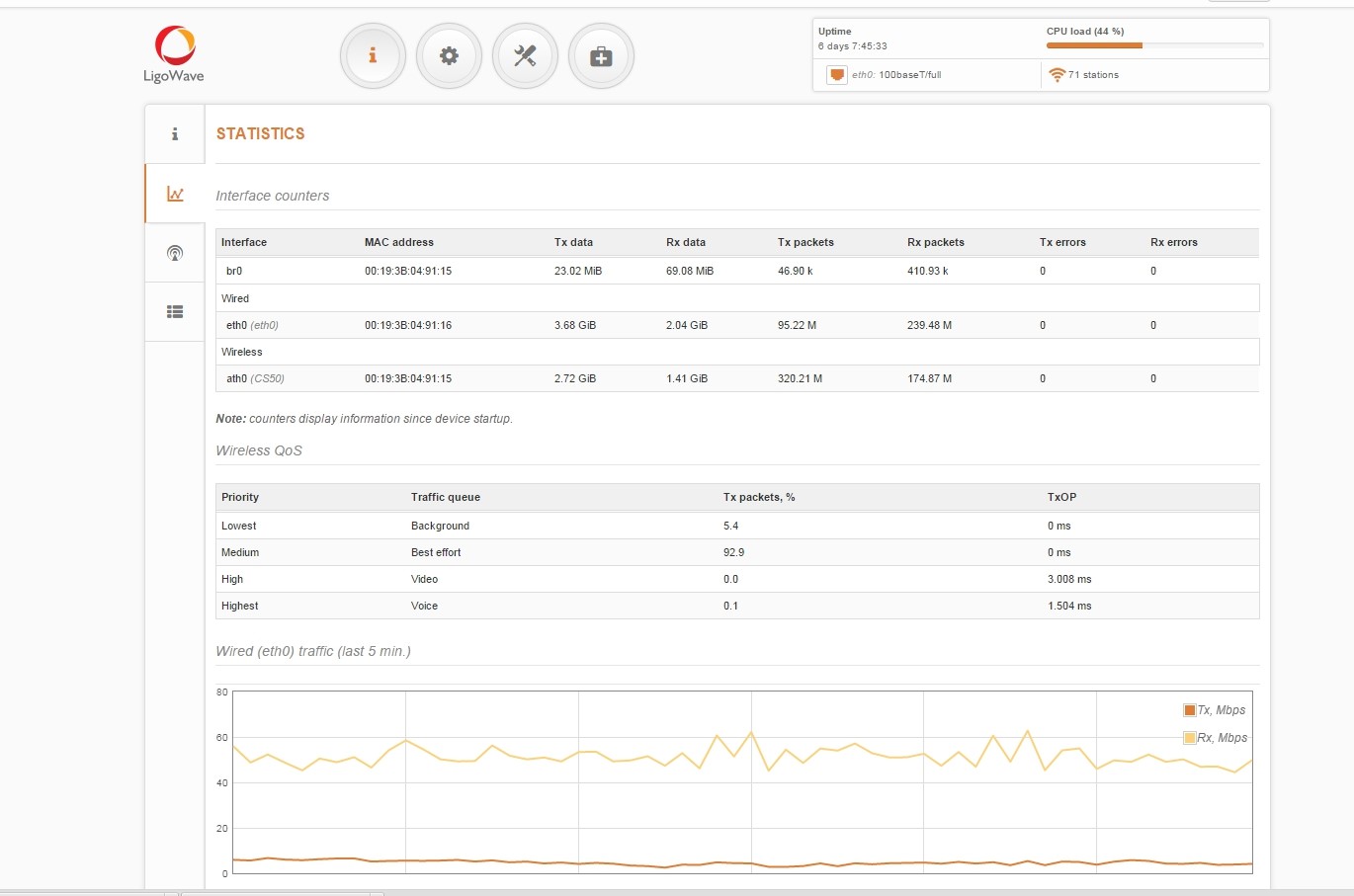
This image is a screenshot of AP’s statistics window, where an administrator can view a real time throughput graph. At that moment the aggregated throughput was about 60 Mbps and most of it was in a direction from AP to CPE (received on Ethernet port). Even with many active stations, the GUI responsiveness was fast and reliable.
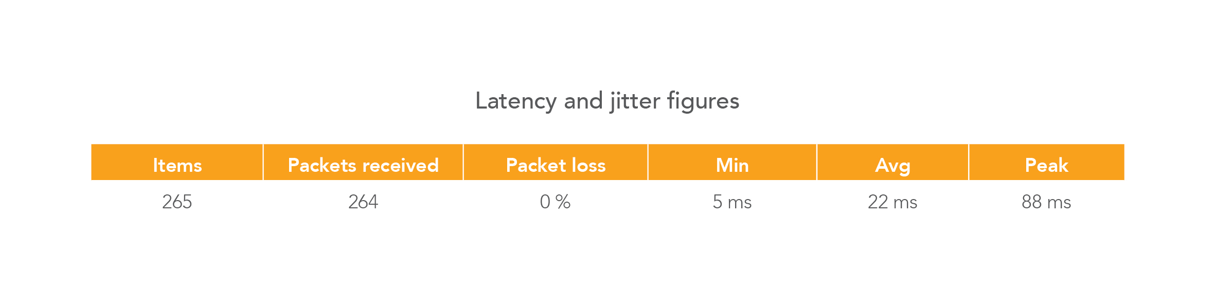
Low latency and stable jitter figures are quite important when providing reliable Internet services. Some of the customers are actively playing on-line games and latency and jitter are critical to ensure a smooth gaming experience. Minimum, average and peak latency figures and 0% packet loss in the table above demonstrates that the LigoDLB series devices meet that challenge even with 70+ clients connected to the access point.
”There are multiple reasons why we chose PTMP equipment from LigoWave. Low jitter and ping and it keeps stable on heavy load access points with high actual throughput. Dual flash memory image makes damaging firmware almost impossible. “Smart channel width” feature makes all the client devices reconnect once the channel size is changed on the base-station. Good monitoring system – WNMS. ”
Aleksandr Suchkov, Linkfor.